
FAQ
General questions
Are Koso meters universal?
All of our products are “universal”, which means they can fit almost any application on the market, except for those that use the CANBUS system.
How to know if your motorcycle uses the CANBUS system? Unplug your OEM meter and try to start your motorcycle.
- If the engine starts and you can run the motorcycle without the OEM meter, then it is not using the CANBUS system, which means any of our meters will work on your bike.
- If the motorcycle does not start without the OEM meter plugged-in, this indicates that it does use the CANBUS system, therefore, our meters will not function on your bike.
Each Koso unit is supplied with the brackets, wires and sensors that you will need for the installation. In order to install our gauges properly, you will need to have the wiring diagram of your application to be able to match our wires with your harness. If you want to know how our gauges are wired, take a look on our website, you will be able to find instructions for each gauge so you will know in advance how to be prepared.
For more information about the CANBUS system call your local dealer.
For more information about the compatibility of the Koso meters, please call our technical support line by dialing 450-359-0604.
Are Koso meters waterproof or water-resistant?
All of our meters are water-resistant. The IP rating is 66, refer to table below for more information:
The IP Code, International Protection Marking, IEC standard 60529, sometimes interpreted as Ingress Protection Marking, classifies and rates the degree of protection provided against intrusion (body parts such as hands and fingers), dust, accidental contact, and water by mechanical casings and electrical enclosures. It is published by the International Electrotechnical Commission (IEC).
Solid particle protection
The first digit indicates the level of protection that the enclosure provides against access to hazardous parts (e.g., electrical conductors, moving parts) and the ingress of solid foreign objects.
| Level | Object size protected against | Effective against |
| 0 | — | No protection against contact and ingress of objects |
| 1 | >50 mm | Any large surface of the body, such as the back of a hand, but no protection against deliberate contact with a body part |
| 2 | >12.5 mm | Fingers or similar objects |
| 3 | >2.5 mm | Tools, thick wires, etc. |
| 4 | >1 mm | Most wires, screws, etc. |
| 5 | Dust protected | Ingress of dust is not entirely prevented, but it must not enter in sufficient quantity to interfere with the satisfactory operation of the equipment. |
| 6 | Dust tight | No ingress of dust; complete protection against contact (dust tight) |
Liquid ingress protection
The second digit indicates the level of protection that the enclosure provides against harmful ingress of water.
| Level | Protected against | Effective against | Details |
| 0 | Not protected | — | — |
| 1 | Dripping water | Dripping water (vertically falling drops) shall have no harmful effect. | Test duration: 10 minutes Water equivalent to 1 mm rainfall per minute |
| 2 | Dripping water when tilted up to 15° | Vertically dripping water shall have no harmful effect when the enclosure is tilted at an angle up to 15° from its normal position. | Test duration: 10 minutes Water equivalent to 3 mm rainfall per minute |
| 3 | Spraying water | Water falling as a spray at any angle up to 60° from the vertical shall have no harmful effect. | Test duration: 5 minutes Water volume: 0.7 litres per minute Pressure: 50–150 kPa |
| 4 | Splashing of water | Water splashing against the enclosure from any direction shall have no harmful effect. | Test duration: 5 minutes Water volume: 10 litres per minute Pressure: 50–150 kPa |
| 5 | Water jets | Water projected by a nozzle (6.3 mm) against enclosure from any direction shall have no harmful effects. | Test duration: at least 3 minutes Water volume: 12.5 litres per minute Pressure: 30 kPa at distance of 3 m |
| 6 | Powerful water jets | Water projected in powerful jets (12.5 mm nozzle) against the enclosure from any direction shall have no harmful effects. | Test duration: at least 3 minutes Water volume: 100 litres per minute Pressure: 100 kPa at distance of 3 m |
| 6K | Powerful water jets with increased pressure | Water projected in powerful jets (6.3 mm nozzle) against the enclosure from any direction, under elevated pressure, shall have no harmful effects. | Test duration: at least 3 minutes Water volume: 75 litres per minute Pressure: 1000 kPa at distance of 3 m |
| 7 | Immersion up to 1 m | Ingress of water in harmful quantity shall not be possible when the enclosure is immersed in water under defined conditions of pressure and time (up to 1 m of submersion). | Test duration: 30 minutes Tested with the lowest point of the enclosure 1000 mm below the surface of the water, or the highest point 150 mm below the surface, whichever is deeper. |
| 8 | Immersion beyond 1 m | The equipment is suitable for continuous immersion in water under conditions which shall be specified by the manufacturer. However, with certain types of equipment, it can mean that water can enter but only in such a manner that it produces no harmful effects. | Test duration: continuous immersion in water Depth specified by manufacturer, generally up to 3 m |
| 9K | Powerful high temperature water jets | Protected against close-range high pressure, high temperature spray downs. | Test duration: – Water volume: 14–16 litres per minute Pressure: [8000–10000 kPa / 80–100 Bar] at distance of 0.1–0.15 m Water temperature: 80 °C |
What is the best way to get reading out of a connector?
To test a connector, install a safety pin inside the connector like showed on picture below:

How to install a battery on the Mini & Mini 3 meters?
1- Locate the metal tab

2- Slide the battery between the bottom and the tab

Warning : Make sure the tab is OVER the battery.
The connection can’t be done if the tab is under the battery.
*** Make sure that the battery is functional. If meter does not turn on, try a new battery (CR2032) ***

3 – Close cover and you’re ready to go !
How to install a battery on the air density meter?
For the battery installation, be careful to place the tabs near the “Close/Open” (battery +) to go over the battery and the other tabs (battery -) to go under it as shown on the pictures:


DO NOT modify the orientation of the pins. The meter will not work if you invert the pins.

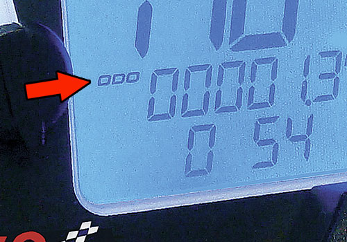
How to access the setting mode on my meter?
All Koso meters need to be set at the odometer to be able to enter setting mode. It will not work if you are on any other function. Then you have to press the ADJUST and SELECT button together for 3 to 5 seconds and you will access the setting mode.
Are there any import taxes or duties when purchasing a product from our website or order line?
Depending on the country in which you are located, the import taxes or duties main vary from one product to another. All duties, taxes or other fees claimed by couriers are at the customer’s expenses.
Specific questions
Harley-Davidson®
What is the torque required for the for Harley-Davidson® engine Oil Plug or Oil Temperature Sensor?
When installing the Engine Oil Plug or Oil Temperature Sensor, use a Torque Wrench to torque from 14 to 21 ft-lb (or from 19 to 28.5 NM).

Where do I install the oil temperature sensors supplied with the HD-03 (part# BA064902 + BA064921 + BA064911) kits?
The larger brass sensor is the oil temperature sensor. This must be installed in the oil pan at the drain plug location.
Honda GROM®/Monkey®
Any Tips & Important notes for the GROM/Monkey 170cc big bore kit and 4v head?
Read this document carefully and retain for future reference. Any failure to respect those conditions can cause engine problems and severe damages.
THIS IS AN AFTERMARKET PART BUILT FOR RACING PURPOSES ONLY. KOSO IS NOT RESPONSIBLE FOR ANY DAMAGES CAUSED TO THE PARTS, VEHICLE, OR TO YOURSELF AND OTHERS. ENGINE PARTS ARE NOT UNDER WARRANTY NOR ARE COLLATERAL DAMAGE NOR COST OF LABOR, IN CASES OF MALFUNCTION.
• Installation of this kit must be done by a professional certified mechanic
• Instructions must be followed accordingly to assure proper installation
• Some modifications or additional parts may be require, refer to table on BACK of this document.
* RPM should be maintained below 12,500 at all time. Over-revolution can cause the valves to hit the piston and damage engine parts.
* Optimal Air/Fuel ratio (14.7) is very important. Running too lean can cause the piston to over-heat and damage engine parts.
* As these parts are made for racing purpose, keeping the throttle wide-open for a long period can cause the engine to over-heat. It is not recommended to travel long distance on the highway.
* Recommended engine oil is Motul 300V 10W40, but customer might have to adjust viscosity (5W / 10W / 15W) depending of the local climate. It is also mandatory to check oil level every ride to make sure that the oil level is correct at all time.
* Recommended fuel is “Unleaded premium grade with high octane”.
* Keep the air filter clean at all time to assure better performance.
* Engine maintenance has to be done more frequently when using racing parts.
* Timing adjustment is very important to avoid pre-ignition.
Additions / Modifications
When using 170cc big bore kit only,
Customer must change or add following parts :
| YES mandatory | Suggested not mandatory | |
| Hurricane Air Filter #DK623000 | X | |
| Throttle body #DY623013 | X | |
| Connecting Tube #DM623000 | X | |
| Rubber intake #DM623K10 | X | |
| Intake manifold #DP623001 | X | |
| Injector #DB008160 | X | |
| Injector adapter #DB623000 | X | |
| Camshaft #MM623002 | X | |
| Hi-Flow oil pump #NF623000 | X | |
| Mini 3 Air/Fuel ratio #BA003214 | X | |
| ECU modification | X | |
| Addition of a fuel control box | X | |
Other Proper exhaust system must be used to prevent re-flow pressure and heat. | X |
When using 170cc big bore kit and 4valves head,
Customer must change or add following parts :
| YES mandatory | Suggested not mandatory | |
| Hurricane Air Filter #DK623000 | X | |
| Throttle body #DY623013 | X | |
| Connecting Tube #DM623000 | X | |
| Rubber intake #DM623K10 | X | |
| Injector #DB008160 | X | |
| Injector adapter #DB623000 | X | |
| Hi-Flow oil pump #NF623000 | X | |
| Spark Plug #NGK-ER9EH | X | |
| Mini 3 Air/Fuel ratio #BA003214 | X | |
| ECU modification ? | X | |
| Addition of a fuel control box | X | |
Other Proper exhaust system must be used to prevent re-flow pressure and heat. | X |
Speedometers & accessories
How to change speed unit from KM/H to MPH?
All our digital speedometers and multifunction meters can display the speed in km/h or MPH. There are two ways to do the switch. Please try option A first, if this is not working, try option B. If you need more information or if you still can’t get it to switch, do not hesitate to contact us 450-359-0604 or info@koso-na.com
How to find the north pole of a magnet?
Finding the north pole on a speed sensor magnet is a very important step in the setting of the speed sensor in order to have a clear reading.

The “N” or the red line indicates the north side of the magnet.
If you can’t find any marks on the magnet, you can use a compass.
The north face of the magnet will always attract the south on the compass.

How to fix a speed accuracy/no display problem?
- The negative pole of the magnet must face the speed sensor (negative side is identified by the letter N or by a ‘’red trace’’ – if unable to determine, please refer to FAQ – How to find the north pole of a magnet
- The speed sensor must be line-up correctly with the magnets – it has to cross center to center
- If using more than one magnet, you need to make sure that there is the exact same distance between each magnet
- The speed sensor must be 1mm to 2mm close to magnets in order to have a reading
- Were you able to calibrate the meter? If the meter has not been set-up you will not see anything on the screen
- If calibration was done, please make sure that the tire circumference was calculated as per instructions. Also, the number of pulses entered must correspond to the number of magnets installed on the wheel
How to test a speed sensor?
- You must calibrate your meter to 2 000 mm wheel circumference and P1. This is only for test purpose. If you don’t know how to enter calibration mode, refer to your meter’s instruction manual on it’s respective page.
- Define your speed sensor type. Touch the tip of the sensor with a metal piece.
- Active speed sensor : the metal piece will stick to the sensor because the active speed sensors are magnetic.
- Passive speed sensor : the metal piece will not stick to it.
- Now you can proceed with the test :
- Active speed sensor : gently rub any metal piece on the tip of the speed sensor.
- Passive speed sensor : gently rub the north pole of a magnet on the tip of the speed sensor. (to find the north pole of a magnet, refer to the previous FAQ
- Results :
- If the speed sensor functions properly, you will see some random numbers on the screen of the meter.
- If speed does not show up, this could indicate a defect sensor. In this case, pls call our tech support line 450-359-0604.
Tachometers & accessories
How to fix the tachometer ‘’bouncing’’ / wrong reading problem?
- Tachometers require a very good ground in order to have a steady signal. Do not ground on the frame, do not use a common ground wire. At first pls ground directly to the negative pole of the battery. If your application does not have a 12 volts battery, pls ground on the engine. Once your tests has been made and meter is functioning properly you may now try to ground elsewhere.
- There is several places to take the RPM signal from. The best place is usually the ignition coil, either the positive or negative side of the ignition coil can do (remember to switch the tachometer to HI or LO when switching from positive to a negative signal – HI for Positive, LO for negative). Another way to take the signal can be the injectors, the pulse generator or wrapping the RPM wire around the spark plug wire.
- Pls note that if you haven’t calibrated the tachometer you will not see any reading. Calibration is important and requires a careful look at the instructions. Some changes may be required, as an example, a 2 stroke 1 piston application might require the setting of a 4 stroke 2 pistons, it all depends of the ignition system. Also, when will be the time to set the meter on HI or LOW, remember that a positive input must be set on HI and negative input on LOW.
- Some application might require the use of an adjustable RPM signal filter.
- If you still experience tachometer problems after trying all those hints above, contact our tech support 450-359-0604 or via info@koso-na.com
Air/Fuel Ratio meters & accessories
Do you have a guide for installing a Wideband Air/Fuel ratio meter?
Warning !!!
This wideband air/fuel meter must be installed by a certified mechanic. Koso North America is not responsible for any damages that might be cause to the vehicle or its users during of following the installation.
- Do not cut or modify the sensor or wiring harness
- Do not connect or disconnect the sensor when the instrument is working
- Do not apply voltage above 18 volts DC
- Do not open or modify the instrument or sensor
- This instrument should be used as a tuning tool or race instrument.
- Connect the instrument only on 12 volts DC power
- Due to the nature of its use, the BOSCH LSU4.2 sensor is not covered by any warranty.
- Koso air/fuel ratio instrument is covered for any manufacturing defect for a period of 6 months following the date of purchase
Wideband Air/Fuel ratio meter facts
The first role of and oxygen sensor is to communicate to the ECU or the gauge if the engine is running lean or rich. The goal is to have the motor run at 14.7 parts of air for 1 part of fuel (Lambda 1). Having the engine running at 14.7 to 1 would represent the optimal exhaust combustion.
O2 sensor facts
The Koso wideband air/fuel ratio meter is currently using the BOSCH LSU4.2 sensor. The 5 wires wideband oxygen sensor is the most accurate sensor on market. This sensor is able to read from10.0 to 24.0 to 1. The operating temperature of the sensor should not exceed 1 700 degree F. Using the sensor with leaded fuel or on 2 strokes engine will shorten the life of the sensor. Using a sensor bung adaptor will help extend the life of the sensor.
Calibration of the instrument
Each BOSCH LSU 4.2 oxygen sensor is individually laser trimmed with is own value for better results. The LSU 4.2 sensor is using a unique ‘’breather’’ system located on the connector (figure 1) to calibrate himself. This mean the sensor is self calibrating with the ambient air so there is no need to calibrate the sensor. This process replace the ‘’free air’’ calibration procedure when changing the sensor or using the unit on another exhaust system was needed. It would be very important not to block the cap above the breather (figure 2) due to the fact that the sensor is self calibrating by ‘’breathing’’ air from this hole.


Oxygen sensor installation
According to the oxygen sensor manufacturer, for better results, the sensor should be installed at the warmest location on the exhaust system. This would usually represent the first part of the exhaust which would be 300 to 500 millimeters from the piston skirt (figure 3). On a 2 strokes engine, it is strongly recommended to use a sensor bung adaptor to lower the impact of oil contamination (figure 4) on the O2 sensor. The sensor should be assembly with high temperature non permanent grease and tighten at 40-60 Nm. The use of cleaning fluids at the sensor plug is not permitted. Avoid any water or condensation on the tip of the sensor otherwise it might damage the internal components. Sensor must be installed with an angle of at least 10 degree (figure 5). Thus preventing the collection of liquids between sensor housing and sensor element during the cold start phase.


How to troubleshoot a wideband AFR sensor (28-BOSCH)
There is 2 quick tests to verify if the sensor is operational.
1- Continuity test
* This test is done on the sensor only.
Use a multimeter to test the Ω of the sensor’s connector at ambient room temperature.
Sensor’s Connector |
Sensor’s Connector Positions |


If reading appear on the multimeter, this indicates that the continuity is good, therefore the sensor is OK. At room temperature, the reading is between 2.5 and 5Ω.
If OL (open lead) shows on the multimeter chances are that the sensor would be defective.
* If test 1 fails, do not attempt test 2.
2- Operational test with butane
* This test is done with meter connected to 12V DC power and sensor connected to the meter.
When you turn on the meter, the first thing to display in the screen is the version of the software.
R8 will indicate that this is the latest updated version. If display shows R7, R6 or less, this means that the meter is over 5 years old.

BA004068 Wide band AFR meter
The meter will then go through its starting set-up by going up to 100 and ready to operate. You may start the test.
Use a butane torch and get the sensor very close to the tip of the torch (you can use a mechanic glove as a kind of seal). Be careful, the sensor becomes hot. Turn on the torch BUT DO NOT LIT THE FLAME. Sending butane to sensor should show reading on the meter (reading vary depending of the quantity of butane sent).

Butane Test
If you have reading on the meter by doing this butane test, it indicates that the sensor is working fine. If not, chances are that the sensor appears to be defective.
EGT meters & accessories
Need tips for Installation of EGT sensors?
The temperature indicated on your meter is the temperature at the tip of your exhaust sensor. This temperature is different for each sled on the market.
An engine should never be tuned by exhaust temperature alone. The exhaust gas temperatures are a great tuning aid but they are not the final word. The normal temperature range for most sled will range between 1100°F and 1250°F depending on the engine setup. The temperature indicated should always be correlated with the piston and plug color. Generally, probe location should be between 4 to 6 inches from the piston skirt, the sensor should be 1/4 inch deep into the pipe and the size of the hole should be 1/4 inch. Each sled and exhaust systems manufacturer have their own specifications for probe location and running temperature. To be more precise, these manufacturing companies should be contacted for all the details needed.

How to distinguish a standard and fast response EGT sensor?
The main difference between the 2 types of EGT sensors is the tip. The standard EGT sensor has a round tip and the fast-response EGT sensor has extended tip that looks like a drop. Another difference is the color of the shrink which is black on the fast response and red for the standard.

How to test an EGT sensor?
Testing an EGT sensor is quite simple.
- Make sure that the sensor is connected to the meter and that the meter is turned on
- Testing will require a very high temperature source so you can use a heat gun or a butane torch
- Heat the tip if the sensor as pictured below
***You must remember that the meter will show temperature over 250°F only.***


Conclusion
If you see a reading over 250ºF then the sensor should be OK
If you see ” – – L – – ” on the meter, check the Omega connecter – (check the other FAQ).
If you see only ” – – – – – ” pls call our tech support 450-359-0604

EGT Meter
How to verify the EGT sensor connector?
When the temperature red by the EGT sensor is under 250°F, the meter shows ” – – L – -“.
If the temperature is over 250°F and the meter is still showing ” – – L – – “, the sensor(s) must be checked
Here’s the yellow connector to verify:

With the use of a small screwdriver, open the connector. Verify that the two wires are placed as shown and that they do not touch each other. If the wires are touching each other, replace them correctly as shown on below photo, then close the connector.

Temperature meters & accessories
What is the torque required for the for Harley-Davidson® engine Oil Plug or Oil Temperature Sensor?
When installing the Engine Oil Plug or Oil Temperature Sensor, use a Torque Wrench to torque from 14 to 21 ft-lb (or from 19 to 28.5 NM).
Heated Thumbs
How to install the heated thumb: Visual representation
Step 1 Step 2
 Step 3
 Step 4
  Step 5
 Step 6
 Step 7
Heated grips verification
All tests should be done with a multimeter. Make sure to have your ground (black) probe on the negative side of the battery when testing the voltage. These tests can be completed with the grips installed, so please do not remove them until testing is complete.
Continuity check
Picture 1: Check for continuity in grips
To confirm you have continuity, you should see a resistance reading or hear a beep in the multimeter. If there is no continuity, the multimeter will indicate “open lead”, which indicates a problem with the grips.

Picture 2: Heated thumb continuity check
To confirm you have continuity, you should see a resistance reading or hear a beep in the multimeter. If there is no continuity, the multimeter will indicate “open lead”, which indicates a problem with the heated thumb.


Voltage check
Picture 1: Check connector to confirm reading above 12v + DC

Picture 2: Controller harness, confirm reading above 12v + DC in connector

Apollo heated grips check
Picture 1: Apollo heated grip continuity check
To confirm you have continuity, you should see a resistance reading or hear a beep in the multimeter. If there is no continuity, the multimeter will indicate “open lead”, which indicates a problem with the grips.

Picture 2: Check for reading above 12v + DC in connector

Picture 3: Check pin on connector for reading above 12v + DC (bottom right pin)

Picture 4: Check pin for reading above 5v + DC (bottom left)

Picture 5: Check on first side of fuse to confirm voltage and there is no issue with the fuse

Picture 6: Check other side of fuse to also confirm there is no issue

Vérification des poignées chauffantes
Tous les tests devraient être effectués avec un multimètre. Assurez-vous de placer la sonde du multimètre (noire) sur le côté négatif de la batterie lors du test de voltage. Ces tests peuvent être complétés avec les poignées installées. Veuillez donc ne pas les enlever avant la fin de la vérification.
Test de continuité
Image 1: Test de continuité pour poignée chauffante
Pour confirmer qu’il y a continuité, vous devez lire une résistance sur le multimètre ou entendre un son aigu. S’il n’y a pas de continuité, le multimètre indiquera que le circuit est ouvert (“open lead”). Cela signifie qu’il y a un problème avec les poignées.
Image 2: Test de continuité pour pouce chauffant
Pour confirmer qu’il y a continuité, vous devez lire une résistance sur le multimètre ou entendre un son aigu. S’il n’y a pas de continuité, le multimètre indiquera que le circuit est ouvert (“open lead”). Cela signifie qu’il y a un problème avec le pouce chauffant.

Test de voltage
Image 1: Vérifiez que le raccordement de poignée affiche plus de 12v + DC
Image 2: Vérifiez que le raccordement du contrôle (4 terminaux) affiche plus de 12v + DC
Test de poignées chauffantes Apollo
Image 1: Test de continuité pour poignées chauffantes Apollo
Pour confirmer qu’il y a continuité, vous devez lire une résistance sur le multimètre ou entendre un son aigu. S’il n’y a pas de continuité, le multimètre indiquera que le circuit est ouvert (“open lead”). Cela signifie qu’il y a un problème avec les poignées.
Image 2: Vérifiez que le raccordement de poignées chauffantes affiche plus de 12v + DC
Image 3: Vérifiez que le voltage affiche plus de 12v + DC (coin droit en bas)
Image 4: Vérifiez que le voltage affiche plus de 5v + DC (coin gauche en bas)
image 5: Test sur un côté du fusible pour confirmer le voltage et la fonctionnalité du fusible
Image 6: Test sur l’autre côté du fusible pour confirmer encore une fois le voltage et la fonctionnalité du fusible
Video Tutorials
(Setting up parameters)
GPS Lap Timer tutorial
These GPS Lap Timer video tutorials will show you how to set the parameters.
HD-03 meter kit tutorial
These HD-03 meter kit video tutorials will show you how to set the parameters.
TNT-B meter for Yamaha Bolt tutorial
These TNT-B meter for Yamaha Bolt video tutorials will show you how to set the parameters.